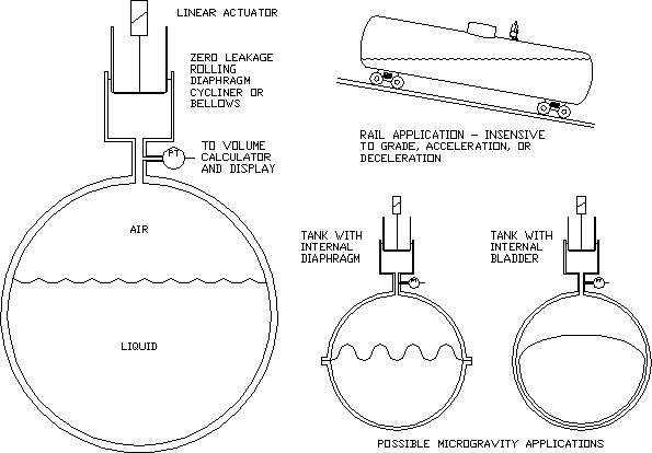
This scheme was originally developed for a railroad tank car application. The request was for a minimally invasive volume measuring system that would be insensitive to the inclination, acceleration, and deceleration which rule out traditional metering methods. The method here works on sealed tanks of a standard compressible fluid with the remainder of the space taken up by a normal gas. The vapor pressure of the fluid must not be significant compared to the gas pressure. For instance, this will not work for a tank completely full of Freon and Freon vapor at equilibrium.
The idea is to periodically compress the gas slightly with a known displacement zero-leakage cylinder or bellows and measure the relative pressure change with a pressure transducer/transmitter. The compression should not be great enough to significantly change the gas temperature, which would otherwise need to be compensated for. The static pressure of the tank does not matter as long as it is stable, but it affects the design of the piston actuator. For a perfectly sealed pressurized tank, monitoring the gas pressure alone yields the remaining fluid volume. This scheme can differentiate between a gas leak and an actual reduction in liquid volume.
As the total tank volume T, the piston displacement D, the low pressure L, and the high pressure H are known, the liquid volume V is easily calculated using Boyle’s law:
V = T – L * D / (H – L) Note that this is completely independent of the shape of the tank.

Implementation using a tank with an internal diaphragm or bladder might have applications in a microgravity environment.
